Sewing machine tension is a system for controlling thread resistance and temporary slack, not simply a number on a dial. On a typical domestic lockstitch machine, the upper thread passes through guides, tension discs and the take-up system, while the lower thread meets its own controlled resistance at the bobbin area. The presser-foot position can change the state of the upper tension discs before any setting is changed, and automatic tension can use a different control architecture from a manual regulator. Understanding those separate jobs makes the mechanism easier to trace without drifting into adjustment or fault diagnosis.
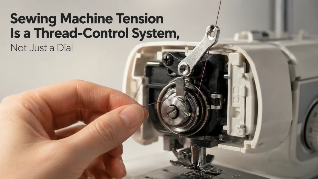
One thread path can have two different presser-foot states
So, how does sewing machine tension work before anyone touches the tension control? Start with a simple state change documented by Janome: raising the presser foot opens the upper tension discs for threading. The thread path may look unchanged from the outside, but the part gripping the thread has changed state.
That distinction matters because resistance is not created by the dial number alone. The regulator, the discs, the thread path and the presser-foot-linked release have to be considered as a system. A first-time owner can easily assume that the thread should feel the same with the foot raised and lowered, even though the machine is designed to alter disc engagement between those states.
Key point: Presser-foot position can change whether the upper thread is being gripped by the tension discs. That is a mechanism state, not a recommended setting and not a universal troubleshooting test.
This article stays at that mechanism level. It explains where resistance comes from and how slack is handled through the stitch cycle, while adjustment procedures, cleaning hidden assemblies and symptom-led fixes belong elsewhere.
Define tension as controlled resistance, not tightness everywhere
The most useful way to understand thread tension is as controlled resistance to thread movement. The machine needs thread to move when the needle carries it toward the hook, but it also needs enough restraint and take-up action to prevent uncontrolled slack and to seat the completed lockstitch. Calling the whole process simply “tight thread” hides those different jobs.
This is why the sewing machine tension mechanism includes both relatively steady resistance points and moving parts. Tension discs can resist upper-thread movement, a lower-thread spring can resist bobbin-thread delivery, and the take-up system changes how much upper thread is available at different moments. Those functions overlap in the finished stitch, but they are not mechanically identical.
Locate the upper and lower sources of resistance
On a typical domestic lockstitch machine, the upper thread is routed from the spool through guides, through or between the sewing machine tension discs, into the take-up path, then down toward the needle. The lower thread leaves the bobbin through a controlled path in the bobbin holder or bobbin case assembly. The exact shape, visibility and terminology of these parts vary by model.
The two threads therefore do not receive resistance from one shared component. Upper-thread resistance and lower-thread resistance are generated in different parts of the machine, then interact when the lockstitch is formed and seated. That is why a balanced stitch should not be described as two controls being mechanically identical.
- Upper-thread resistance: the tension discs and regulator control resistance in the upper path when the discs are engaged.
- Upper-thread slack management: the check spring, where used, and the take-up lever respond to changing thread demand without becoming a second tension dial.
- Lower-thread resistance: the bobbin-side spring path applies its own resistance as lower thread is delivered.
Use that map to separate components before trying to name a problem. If the question is about which part applies resistance, look at the thread path; if it is about when thread is needed during stitch formation, the moving take-up system becomes central.
Follow the upper thread through guides, discs and regulator
The upper thread first has to reach the resistance system in the intended route. Guides position the thread so it enters the next component correctly, while the tension discs provide a controlled gripping interface. On a manually controlled machine, the user’s tension input changes the regulator state that affects how strongly that upper-thread path is restrained.
The important distinction is between a control and the resistance-producing hardware it influences. A numbered dial is an interface. Behind that interface, the tension discs and regulator are the parts that change upper-thread resistance, and their exact construction can differ among models.
| Upper-thread path | State to identify | Reason it matters |
|---|---|---|
| Spool to thread guides | Thread follows the documented route | Later resistance assumes the thread reaches the control system correctly |
| Tension-disc area | Discs released or engaged | Threading and sewing can use different disc states |
| Take-up path | Thread seated in the moving take-up component | The cycle depends on controlled release and recovery of upper thread |
| Needle-side guides | Thread remains in the specified path | The needle must receive thread from the controlled path above it |
That path is a mechanism map, not a generic threading instruction for every machine. The exact manual should remain the authority for where the thread goes on the model in front of you.

Gutermann Sew-All is a 100 percent polyester general-purpose sewing thread for machine and hand sewing. The manufacturer lists it for closing seams, topstitching, and decorative stitches across a broad range of fabrics. Gutermann specifies Universal needles in the NM 70 to 90 range for this thread, while the exact machine and project should still determine the final setup.
Check On AmazonIf you click this link and buy, we earn a commission at no additional cost to you.
The presser-foot-linked release changes disc engagement
Janome’s current technical support tells owners to raise the presser foot before threading the upper path because doing so opens the tension discs. Brother also tells owners across a listed family of domestic models, including the CP100X and CS7000X, that the presser foot must be raised so thread can enter the tension disc. These instructions show that the foot lever can affect the tension assembly even though it is not itself a tension control.
That mechanism explains an otherwise confusing observation: the same thread can encounter different resistance without the user moving the numbered control. The changed variable is the release state linked to the presser foot. This is also why the exact model instructions matter, because the linkage may be hidden and the user may only see the external lever and thread path.
Separate the check spring from the take-up lever
A check spring and a take-up lever can both affect the upper thread, but they should not be collapsed into one vague “tension part.” On machines that use a visible or hidden check spring arrangement, the spring reacts over a smaller movement range to manage changing thread demand and slack around part of the stitch cycle. The take-up lever travels through a much larger repeated motion tied to the needle mechanism.
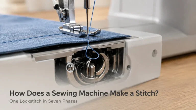
The take-up lever’s role is easier to understand when connected to the lockstitch formation sequence. As the needle and hook create and pass the upper-thread loop, the machine cannot keep the upper thread equally short and taut at every instant. The take-up system allows the necessary thread movement, then recovers excess thread as the cycle advances.
Thread demand rises during needle descent and loop capture
As the needle descends, the upper thread has to travel with it through the fabric and into the hook area. Near loop formation, the hook needs enough upper thread to catch and carry that loop around the lower-thread system. A mechanism that held the upper thread at one fixed length with no allowance for changing demand would work against this movement.
This is where understanding how sewing machine tension works becomes more precise than describing two threads pulling against each other. Resistance still matters, but thread availability also changes with the cycle. The take-up mechanism and any spring-based slack control help the machine supply thread when the stitch needs it rather than treating every moment as a constant-resistance event.
| Cycle phase | Upper-thread demand | Take-up role |
|---|---|---|
| Needle descending | Thread is carried toward and through the material | Allows thread to move into the forming stitch |
| Loop presented to hook | Enough thread must be available for loop capture | Does not prematurely remove the loop the hook needs |
| Loop passes around lower-thread area | Upper thread temporarily occupies a larger path | Prepares to recover the extra thread as the cycle continues |
| Needle and take-up rise | Temporary slack is no longer needed | Recovers upper thread and helps seat the stitch |
This cycle view keeps two questions separate: how much resistance the path applies, and how much thread the stitch needs at a particular instant. Both affect the finished lockstitch, but they are not the same variable.
Slack is removed as the stitch is seated
Once the hook has carried the upper-thread loop around the lower-thread area, the temporary extra length is no longer needed. As the take-up lever rises, it recovers that thread from below the needle plate. Resistance in the upper and lower paths influences how the interlock settles as the stitch is seated.
The key point is timing, not a second increase in a static “tightness” value. The lever’s upward motion removes thread that was deliberately available earlier in the cycle. That closes the slack-management phase without turning the take-up lever itself into a tension regulator.
The lower-thread spring provides a separate resistance path
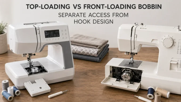
The bobbin thread follows a much shorter route than the upper thread, but it still encounters controlled resistance before entering the stitch. Depending on the machine architecture, the thread passes through a slot, under a spring or through another specified path in the bobbin holder or bobbin case. That spring-loaded path is the lower-thread side of the tension system.
For a first-time owner, the common misunderstanding is to treat the bobbin as a passive spool with no controlled thread path. It is not. The lower-thread assembly matters mechanically, which is why the bobbin mechanism and thread path should be understood before assuming the upper dial is the only source of resistance.
Warning: This mechanism explanation is not an instruction to alter a bobbin case screw, open hidden covers or work around moving or energized parts. Use the exact model manual for owner-level access, and stop for qualified service after a hard mechanical lock, repeated hard needle strikes, smoke, a burning odor, sparks, exposed wiring or uncontrolled motion.
The useful takeaway is simply that upper and lower resistance originate in separate assemblies. Adjustment procedures require model-specific instructions and are outside the scope here.

Brother SA156 is a genuine 10-pack of clear plastic Class 15-type bobbins. Brother specifies these bobbins as 7/16 inch deep and publishes an exact compatibility list for supported sewing and embroidery machines. Check the machine model against that list before purchase rather than assuming that another Class 15-looking bobbin is interchangeable.
Check On AmazonIf you click this link and buy, we earn a commission at no additional cost to you.
Balanced resistance does not mean equal dial numbers
A balanced lockstitch is an outcome of the two thread paths working together through the material and stitch cycle. It does not mean the machine has matching upper and lower numbers, and it does not mean both threads experience identical hardware or identical resistance. Many domestic machines do not even present the lower-thread control as a normal user-facing numbered setting.
Understanding how thread tension works on a sewing machine starts with that distinction. The visible control is only one input into one side of the system. The finished stitch also reflects the lower-thread path, the take-up cycle and the physical route specified by the machine, which is why a number by itself cannot describe the entire mechanism.
Manual input and automatic tension can control resistance differently
A manual tension control gives the user a direct input that changes the upper-thread regulator on that machine. The machine may still contain springs, discs and moving take-up parts, but the selected value comes from the user’s control. That is the architecture most people picture when they think of a tension dial.
JUKI documents a different household architecture for automatic thread tension. In its current technology description, the machine adjusts needle-thread tension according to the sewing pattern, with a dedicated stepping motor digitally controlling the rotation angle of a thread-tension cam. That is a concrete example of automatic control changing the mechanism rather than simply hiding a fixed manual dial behind a screen.
| Control architecture | Where the input comes from | What is documented |
|---|---|---|
| Manual upper-thread control | User-selected regulator position | The user changes the input applied to the upper tension system |
| JUKI household automatic-tension example | Machine control based on sewing-pattern parameters | A stepping motor digitally controls the tension-cam rotation angle |
The comparison is about mechanism, not about which system is better. A manual control can be entirely appropriate, and an automatic label only becomes meaningful when the manufacturer explains what the machine actually controls.
An automatic label does not prove one universal mechanism
“Automatic tension” is not enough information to assume that every computerized machine measures, predicts or adjusts thread resistance in the same way. JUKI’s documented household example uses a stepping motor and tension cam, while its broader technology portfolio also describes other active-tension systems for different machine classes. Similar marketing language can therefore sit on top of different hardware and control logic.
For that reason, the label should be treated as a prompt to check the exact model documentation. The useful questions are what the machine controls, what inputs it uses, whether the function changes by stitch or mode, and what remains user-adjustable. Those answers define the architecture more reliably than the word “automatic” by itself.
Read the exact manual before naming hidden components
Domestic machines can hide the tension discs, take-up lever linkage, spring arrangements and release mechanisms behind the front cover. Even when two machines show a similar external dial or threading groove, that does not prove the internal layout is identical. The safest description starts with what the manufacturer identifies for the exact model.
Brother’s support documentation illustrates why model scope matters: one tension article explicitly lists the domestic models it covers, including CP100X and CS7000X, and ties presser-foot position to thread entry into the tension disc. Janome likewise directs owners back to the machine’s user manual while documenting the general relationship between the presser foot, tension discs and take-up lever. The model number is therefore part of the evidence, not a detail to add after the mechanism has already been assumed.
For the wider machine layout around these parts, use the domestic sewing machine parts map rather than treating one front-cover diagram as universal. That keeps component identification separate from internal repair or service work.
Route the next question by mechanism, setting or symptom
Once the parts are separated, the next question becomes easier to classify. A mechanism question asks where resistance comes from or why the take-up lever moves. A settings question asks what value to choose for a particular setup. A symptom question starts with a failed result such as looping, puckering, thread breakage or an abnormal machine state.
This article owns only the first of those paths. If you need the broader sequence connecting tension to the hook, needle and feed system, how a sewing machine works places the tension system inside the complete domestic lockstitch cycle.
| Your question | What to identify next | Boundary |
|---|---|---|
| Where does thread resistance come from? | Discs, regulator, springs and thread path | Mechanism explanation |
| Why does the take-up lever move? | Changing thread demand through the stitch cycle | Mechanism explanation |
| What number should I use? | Exact machine, material, stitch and thread setup | Setting guidance, not covered here |
| Why are loops or puckers appearing? | Exact symptom, threading state, material and machine condition | Fault diagnosis, not covered here |
Keeping those paths separate prevents a mechanism explanation from quietly turning into a universal fix. It also makes the manual more useful because you know whether you are looking for a parts diagram, a normal-use setting or a troubleshooting procedure.
Final Thoughts: trace resistance and slack separately
Sewing machine tension makes more sense when you stop treating the dial as the whole system. The upper discs and regulator create controlled resistance, the presser-foot linkage can release those discs, the take-up system manages changing thread demand, and the bobbin side contributes its own resistance path.
From there, keep the questions in the right order. Identify the exact machine and documented thread path first, separate resistance from take-up motion second, and only then move to model-specific settings or symptom diagnosis when that is actually the problem you need to solve.
Frequently Asked Questions
These questions stay focused on what the tension system is doing mechanically. They do not replace the exact model’s threading, setting or service instructions.
🧵 What do sewing machine tension discs actually do?
They apply controlled resistance to the upper thread when engaged. The amount and control method depend on the machine’s regulator and architecture, so the visible dial or display is only the user interface to that system.
🦶 Why does raising the presser foot affect upper threading?
On machines using a presser-foot-linked tension release, raising the foot releases or opens the tension discs so the thread can enter the intended path. Janome and Brother both document this relationship for machines within their stated support scope.
⚙️ Is the take-up lever the same thing as the tension control?
No. The take-up lever is a moving part that releases and recovers upper thread through the stitch cycle, while the tension control changes resistance in the upper-thread path.
🪡 Does balanced tension mean the upper and lower settings are equal?
No. The upper and lower threads use different resistance paths, and many domestic machines do not expose matching numbered controls for both sides. Balance describes the resulting stitch relationship, not equality between two dial numbers.
💻 Does automatic thread tension work the same on every computerized machine?
No. JUKI documents one household implementation that uses a stepping motor to control a tension cam according to sewing-pattern parameters, but that does not establish a universal architecture for other models or brands. Check the exact model documentation.
If your question has shifted from what a component does to what setting to use or why a stitch is failing, you have moved beyond mechanism and into a different decision path.
References and Sources
This mechanism explanation uses manufacturer documentation where component state or control architecture needs external verification.
- Janome Technical Support: verifies that raising the presser foot opens the tension discs for upper threading and identifies the take-up lever as part of the documented thread path.
- Brother tension support: verifies the presser-foot and tension-disc relationship for its listed domestic models, including CP100X and CS7000X.
- JUKI Core Technologies: documents a household automatic-tension architecture in which a dedicated stepping motor digitally controls the rotation angle of a thread-tension cam.
These sources support the specific mechanism claims above. They do not make one manufacturer’s threading path, hidden component layout or automatic-control design universal across domestic machines.